This section contains information about which node each network card belongs to, what the IPMIs are for, which one should be connected to each switch and the default IPs.
Each node has two or three RJ45 connections, depending on the model. Each connection has a specific function:
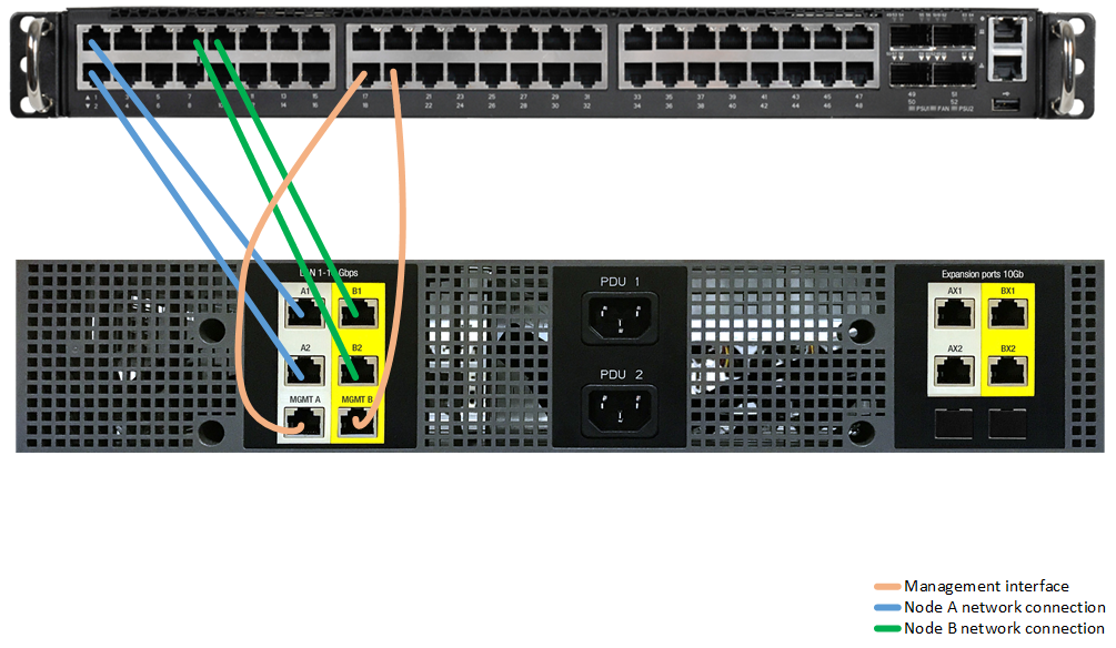
External: these are A1 or A2 (node A), designed to provide network connectivity throughout the infrastructure and to the VDIs and SDIs in it.
Management (IPMI): this interface is designed to permit connection to the node, even if it is switched off.
Depending on the application model, each one has two or three cards:
Demo model (NFR): this model has one adapter, which is connected to the switch (external) and another adapter for management.
Other models: these have two network adapters for service (external) in teaming and an adapter for management.
Connection
The images below shows an example of how to connect the appliance. If a specific switch is available for management, the MGMT cables should be connected to the required switch.
Cookies are important for you, they influence on your browsing experience, they help us to protect your privacy and allow us to proceed with your requests that you demand through the website. We use our own and thirdparty cookies to analyze our services and provide you with advertising related to your preferences on the basis of a profile made with your browsing habits (for example, visited pages). If you consent to its installation, click on "Accept Cookies", or you can also set your preferences by pressing "Cookie settings". More information in our
"Cookies Policy".
Cookies policy
The purpose of this cookies policy is to provide clear and precise information about the cookies used on our website.
We use our own and third-party cookies to improve our services, customize our website, make it easier for our users to browse, offer an improved experience when using the website, identify problems and thereby improve the website, carry out measurements and usage statistics and show you advertising related to your preferences by analyzing the use of the website.
We inform you that we can use cookies on your device provided you have given your consent, except in those cases where the cookies are necessary to browse our website. If you give your consent, we will be able to use cookies that will allow us to gather more information about your preferences and customize our Website according to your individual interests.
WHAT ARE COOKIES?
Cookies and other similar technologies, such as local shared objects, flash cookies, or pixels, are tools used by Web servers to store and recover information about website visitors, and also to ensure the correct functioning of the website.
TYPES OF COOKIES
Types of cookies depending on the organization managing them:
Own cookies: these cookies are sent to the user’s terminal from a computer or domain managed by the owner of the website from which the service requested by the user is provided.
Third-party cookies: these cookies are sent to the user’s terminal from a computer or domain not managed by the owner of the website from which the service requested by the user is provided, but by another organization that processes the data obtained through the cookies. In addition, if the cookies are installed from a computer or domain managed by the Website owner but the information collected by them is managed by a third party, they will also be considered third-party cookies.
Types of cookies according to their purpose:
Technical cookies: these are cookies that allow the user to browse a website, platform or application and to use the different options or services thereon, including those that the editor uses to allow management and operation of the website and enable its functions and services. These include, for example, monitoring traffic and data communication, identifying the session, accessing restricted access areas, remembering the component elements of an order, carrying out the order purchase process, managing the payment, monitoring any fraud associated with the security of the service, dealing with an application for registration or participation in an event, counting the number of visits for the purposes of invoicing licenses for the software with which the service operates (website, platform or application), using security elements during browsing, storing content for the dissemination of videos or sound, enabling dynamic content (for example, animation to load a text or an image) or sharing content on social networks. This category also includes, because of their technical nature, those cookies that allow the management, as efficiently as possible, of any advertising spaces that, as one more element of design or “layout” of the service offered to the user, the editor has included on a website, application or platform based on criteria such as the content edited, without compiling information about the users for other purposes, such as customizing this advertising content or other content. Preference or customization cookies: these cookies are used to remember information so that the user can access the service with certain characteristics that differentiate his/her experience from that of other users such as for example, the language, the number of results displayed when the user performs a search, the appearance or content of the service depending on the type of browser used by the user to access the service or the region from which he/she accesses the service, etc. Analytics or performance cookies: these cookies allow the person or entity responsible for them to monitor and analyze the behavior of users of the websites with which they are associated, including quantifying the impacts of adverts. The information collected by this type of cookies is used to measure activity on the website, application, or platform, in order to introduce improvements according to the analysis of the users’ data usage.
Behavioral advertising cookies: these allow us to manage, as efficiently as possible, the advertising spaces on the website. These cookies store information on user behavior obtained through continuous observation of his/her browsing habits, allowing us to develop a specific profile to show the advertising adapted to that profile.
Geolocation cookies: these are used to find a user’s location when he/she requests a service. These cookies are anonymous and are used, for example, to offer you relevant information depending on the country where you are located.
Types of cookies according to the length of time they remain active:
Session cookies: these cookies are designed to collect and store data when the user accesses a website. They are generally used to store information that only needs to be kept for the provision of the service requested by the user on a single occasion (for example, a list of products bought) and disappear when the user logs off or ends the session.
Persistent cookies: with these cookies, the data continue to be stored in the terminal and may be accessed and processed for a period defined by the person/entity responsible for the cookie, which may range from a few minutes to several years.
COOKIES USED ON OUR WEBSITE
Name
Owner
Duration
Purpose
_helpjuice_session_v2
Technical Cookie
Session
Same-site connections only.
current_user_language
Technical Cookie
Session
Same-site connections only.
user_id
Technical Cookie
Session
Same-site connections only.
_lang
Technical Cookie
1 year
Same-site connections only.
DISABLED IN BROWSERS?
The user can, at any time, allow, block or delete the cookies installed on his/her device by changing the settings on the browser installed on his/her computer:
For more information, consult Apple support or your browser Help.
If you deactivate the cookies, it will not prevent you from browsing the website, but the use of some services may be limited and, consequently, your browsing experience may be less satisfactory.
WITHDRAWING CONSENT
The user may withdraw his/her consent relating to the Cookies Policy at any time and may delete the cookies stored on his/her device by adjusting his/her internet browser settings, as described above, and also by accessing our settings panel:
COOKIE SETTINGS
This Cookies Policy may be modified when required by the legislation in force at any time or when there is a change in the type of cookies used on the website. For this reason, we recommend that you review this policy every time you access our website so that you are appropriately informed of how and why we use cookies.
Cookies settings panel
This is the advanced settings system for own and third-party cookies. Here you can modify parameters that will directly affect your browsing experience on this website.
Technical cookies (required)
These cookies are important to give you secure access to areas with personal information or to recognise you when you log on.